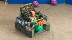
The victory of a student-built basketball-playing robot in a regional technology competition is frequently reported as a heartwarming triumph of youth ingenuity. This framing misses the entire structural reality. Winning a competitive robotics engineering event is not a function of inspiration; it is an optimization problem balancing mechanical efficiency, software latency, and resource constraints under a fixed deadline.
To understand why a specific system outperforms its peers, we must strip away the narrative and analyze the machine as a industrial prototype. The success of a sixth-form (pre-university) engineering team relies on solving three core subsystems: kinematic energy transfer (the shooter), computer vision localization (the targeting), and chassis stability (the drivetrain). When these systems operate in harmony, the robot achieves high repeatability—the only metric that matters in a competitive environment.
The Kinematics of Precision Projectile Delivery
The primary objective of a basketball-playing robot is to maximize the probability of scoring from variable distances. In mechanical engineering, this requires minimizing variance in initial velocity ($v_0$) and release angle ($\theta$). Competitor analysis shows that lower-tier teams often attempt to emulate human shooting form via complex, multi-jointed catapult arms. These systems introduce massive failure points due to backlash in the gears and structural flexing.
The optimal solution utilizes a dual-wheel counter-rotating flywheel mechanism.
This architecture converts rotational kinetic energy into linear kinetic energy through friction. The physics governing this transfer can be modeled by analyzing the moment of inertia ($I$) of the flywheels and the energy drawdown during the launch sequence:
$$\Delta E = \half I (\omega_{initial}^2 - \omega_{final}^2)$$
Where $\omega$ represents the angular velocity of the wheels.
The Recovery Time Bottleneck
A critical flaw in basic flywheel designs is velocity sag. When a ball passes through the flywheels, it compresses, absorbing energy and slowing the motors. If a robot attempts a rapid second shot before the motors spin back up to target RPM, the projectile will fall short. High-performing teams mitigate this through two distinct engineering choices:
- Mass Distribution (Inertia Tuning): Increasing the mass of the flywheel outer rim raises its moment of inertia. A higher $I$ means the wheel resists deceleration during the launch phase, maintaining consistent velocity even if motor torque dips temporarily.
- Closed-Loop PID Control: Instead of sending a raw voltage to the motors, the control system continuously reads encoder data. A Proportional-Integral-Derivative (PID) algorithm calculates the error between actual and desired RPM, adjusting power delivery hundreds of times per second to minimize recovery time.
Computer Vision and Spatial Localization Constraints
A robot cannot score if it cannot accurately calculate its distance from the hoop. In standard student competitions, teams generally choose between two localization paradigms: manual driver alignment or automated vision tracking. Automated systems scale significantly better, provided the team manages processing latency.
The target tracking architecture relies on a pipeline of distinct computational steps:
[Image Sensor Capture] -> [HSV Threshold Filtering] -> [Contour Detection] -> [Distance Extraction via PnP]
1. Color Space Isolation
The camera sensor captures frames in RGB (Red, Green, Blue). Because ambient lighting fluctuates wildly in competition venues, RGB is highly unreliable. Advanced teams convert the image matrix into the HSV (Hue, Saturation, Value) color space. By isolating a specific hue range—such as the reflective green retroreflective tape commonly used on official targets—the software filters out background noise regardless of stadium lighting conditions.
2. Geometric Estimation (Perspective-n-Point)
Once the target's contour is isolated in pixels, the robot must calculate its exact 3D position relative to that target. This is achieved by solving the Perspective-n-Point (PnP) problem. Knowing the real-world physical dimensions of the target and the focal length of the camera lens, the software uses geometry to translate a 2D pixel coordinate into a 3D translation vector ($X, Y, Z$).
This calculation determines the required motor speed for the flywheel. The relationship between distance ($d$) and required velocity ($v$) is dictated by the classic ballistic trajectory formula, accounting for launch angle ($\theta$) and the height differential ($\Delta h$):
$$d = \frac{v^2 \sin(2\theta)}{2g} \left( 1 + \sqrt{1 + \frac{2g\Delta h}{v^2 \sin^2\theta}} \right)$$
The software maps this mathematical curve into a real-time lookup table, eliminating the need for the onboard processor to compute complex trigonometric functions mid-match.
Drivetrain Architecture and Kinetic Stability
A shooter mechanism is only as effective as the platform supporting it. A robot accelerating, decelerating, or turning experiences rapid shifts in its center of mass. If the chassis rocks or vibrates upon stopping, the vision tracking system suffers from motion blur, and the mechanical alignment shifts out of tolerance.
Holonomic vs. Non-Holonomic Drivetrains
Standard drivetrains (like an automobile or a differential-drive tank) are non-holonomic; they cannot move sideways without first turning. This creates an operational bottleneck in a basketball game, where dodging defenders and lining up laterally with the hoop requires fluid motion.
Winning architectures almost universally employ holonomic drivetrains, typically using Mecanum wheels or Omni wheels. Mecanum wheels feature rollers oriented at 45-degree angles around the periphery. By varying the speed and rotational direction of each individual wheel independently, the vector forces combine to move the robot in any direction—omni-directional strafing—without changing its orientation.
The trade-off is friction and efficiency loss. Mecanum wheels slip by design. This means traditional wheel encoders (which count axle rotations to measure distance traveled) become highly inaccurate over the course of a match. Teams operating at a professional level decouple positioning from the drivetrain entirely by implementing independent, unpowered dead-reckoning tracking wheels equipped with optical encoders that drag lightly on the floor surface, measuring true structural displacement.
Resource Procurement and Project Management under Constraints
The technical superiority of a robotics project is ultimately bounded by the team's execution framework. In a secondary education setting, the primary constraints are not just intellectual capacity, but time, budget, and manufacturing access.
The division of labor within an elite six-to-eight-person student team typically mirrors an industrial engineering firm:
| Sub-Team Role | Primary Technical Responsibility | Key Performance Indicator (KPI) |
|---|---|---|
| Mechanical Design | CAD Modeling, Chassis & Shooter Fabrication | Structural deflection under load < 2mm |
| Systems Controls | Wire Harnessing, Pneumatics, Power Distribution | Voltage drop across main bus < 0.5V |
| Software Architecture | Vision Pipeline, Autonomous Pathing, PID Tuning | Loop rate execution speed $\ge$ 50 Hz |
| Strategy & Analytics | Scouting, Cycle Time Optimization, Rules Compliance | Autonomous scoring repeatability $\ge$ 90% |
The Prototype Loop and Risk Mitigation
The definitive failure mode for amateur engineering teams is the "waterfall" development model, where parts are designed, manufactured, assembled, and only then tested sequentially. If a design flaw is discovered during final assembly, the schedule collapses.
Successful teams utilize an agile hardware prototyping loop. They construct crude wood or 3D-printed versions of the shooter within week one to validate the physics calculations. Software engineers write code using emulators or minimal test benches simultaneously. This parallel development compresses the timeline, ensuring that the final integrated machine has at least two full weeks of driver practice and software calibration before entering a competition arena.
Operational Execution Strategy
To replicate or exceed this level of engineering success in a competitive tech environment, institutional programs must shift away from generalized STEM enrichment models and adopt an objective-driven deployment strategy.
Implement a strict component standardization protocol. Do not allow student engineers to custom-fabricate parts that can be purchased off-the-shelf. Using standardized planetary gearboxes, structural aluminum extrusions, and proven motor controllers shifts precious labor hours away from fundamental manufacturing and toward system integration and software optimization.
Enforce a rigid software freeze fourteen days prior to competition. The marginal benefit of adding a new software feature close to competition day is consistently outweighed by the risk of introducing catastrophic bugs into the core locomotion and targeting loops. The final two weeks must be dedicated exclusively to endurance testing, identifying thermal limits of the motors, and building driver muscle memory to handle defensive interference.